FORM INSTRUCTIONS:
- Download the latest “Student RP Request Form“. This form has two sheets the 1st sheet
labeled “Student Request” is for each student to complete (Do not fill out the second Page “CCS Staff Only”, this is for internal use only.) - Fill out course and contact information. List each
stl file to berapid prototyped under the column “File Name.” - No files will be accepted or reviewed without a completed “Student RP Request Form”. All filenames must follow naming instructions (keep names as short as possible)
- Bring your
stl files and completed form on disc or flash drive to the model shop (11th Floor Taubman Building). - All Files must be stitched and
water tight . - Rapid Prototype machines will only accept files saved
in . STL FORMAT.
(stereolithography) - One .stl part per file only. Do not put multiple parts in one part file.
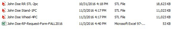
All *** .stl files must contain the student’s full name, how many and located within a folder on the disc or flash drive to be accepted for rapid prototyping. After full student name,
File structure/name conventions – example for submitting rapid prototype file.
Must
- Create Folder zse student’s first and last name only.
- Create STL file(s) John-Doe-
frt –whl -(how many: 1pc, 2pc, etc.) .stl - Stl. files must be saved in
created folder as stated. - Include current RP Reqzuest Form in
folder .
Example of format for submitting files to be rapid prototyped

Create a folder with your name only!
Everything you are submitting goes into this folder.
Add your name to the RP Request form in place of Student (see below) do not change or shorten file name. You must get a new form for each semester with
Your form should look like this, fill out the form and save into folder. You must have your name and contact information. Use only
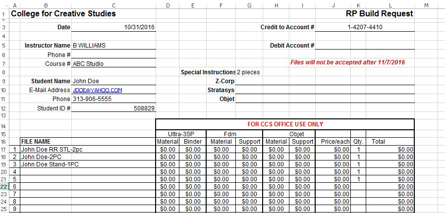
Tips for Building Files
- Build all files to theoretical unless you are confident in your
modeling skills.
Poor surface development from incorporating fillets and radiuses are the
main cause for gaps when attempting to stitch files. - When creating files (parts that will be assembled) remember to include design clearances. If you create your files line for line they will not fit together. For items that will require painting about .010-.012” per side should be sufficient. If pieces will be assembled with light sanding only approximately .005-.008” design clearance will be required.
- When using any of the printers, .060”/1.5mm is the thinnest cross-section recommended if priming and painting are required. The size of the part being created is directly related to wall thickness. Be sure that the integrity of the part will not be affected by thin cross-sections supporting heavier areas
- Build sizes for each machine are as follows:
- Plastic Machine 1 10” x 10” x 12”
- Plastic Machine 2 10” x 10” x 12”
-
Objet Machine 13.5” x 13.5” x 8”
If your part does not fit completely with clearance (4mm) within any of these working envelops it must be split up into smaller pieces which can be glued together later. When splitting parts try to provide split lines with maximum surface area to provide good glue surfaces.
- When creating part geometry small details will be filled during painting. (Lettering) Design these areas/letters to allow for paint buildup to maintain the desired finished appearance. In other words, make them deeper or bigger.
- All extra geometry must be removed (double surfaces and construction geometry blanked entities).
- Some parts may have a large cross-section because of size. The FDM printers can create a semi-hollow interior which reduces the cost and weight of a large part. If the Objet printer is used it cannot create this type of part interior. The best way to reduce cost and weight is to design the part if possible using a surface offset and an access hole which will enable you to clean out most of the support material from inside the part.
- We do not mirror, scale or fix major part problems this is your responsibility. Remember one part per file.
- Make sure your part is the correct scale!
Finishing of Rapid Prototype Parts
- In
general parts can be sanded with 100-240 grit sandpaper prior to typical priming. - Parts created in the Objet printer will need to be cleaned of any leftover support material and surface residue before priming or painting. The procedure for this is to clean all surfaces with the power washer, then alcohol and a stiff brush or cloth depending on how fragile the part. After this
step a light sanding with 120 grit sandpaper is normally all that is required to prep surfaces for priming. - Parts created in the FDM printers will require sanding with 100 grit sandpaper prior to priming.
- Normally at least two coats of primer and sanding in between coats will be required to provide a good surface finish for painting.